
Some CNC turning parts use large taper and thin-walled structural parts. Such products have problems such as large part size, thin wall, poor processing rigidity, easy deformation, difficult clamping and vibration during cutting, which makes it difficult to control the surface quality of parts. , Low processing efficiency.
The structural characteristics of the parts described in this paper are: large taper, long tapered surface and thin wall. Restricted by its own complex structural characteristics, there are the following processing problems in actual processing: ①Clamping is difficult, and the selection of positioning datum, clamping method and clamping position seriously affects the machining accuracy of parts. ②Easy to deform. The bracket is a typical thin-walled structural part. With the removal of material during processing, internal stress and thermal stress cause deformation, and the tool vibrates severely during processing. ③Hyperbolic errors are prone to occur during processing, and processing accuracy and efficiency are difficult to guarantee. According to the processing characteristics of the structural part, through the design of special internal and external positioning tooling, the processing method of the part is improved, the cutting parameters are optimized, the processing bottleneck of the medium and large thin-walled structural part is effectively broken, and the mass production of the part is realized.
Structural features of parts
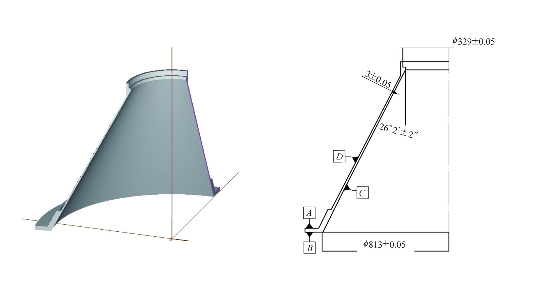
The material of the parts is cast aluminum alloy (ZL205\T6). The process requires the diameter of the small end (329±0.05) mm, the diameter of the large end (813±0.05) mm, the large thin-wall inclination angle of 26°2′, and the wall thickness (3±0.05) mm, the overall height is (587±0.05) mm, and the flatness of the B end face is required to be 0.1mm. The product structure is shown in Figure 1.
For the thin-walled structure with large cone angle, special inner shape processing brackets and outer shape processing inner cone tires are designed, which can effectively enhance the rigidity of the product during processing. The positioning and clamping scheme is adopted to ensure high product positioning accuracy, reliable clamping, and minimal deformation caused by clamping force.
To solve the problem of product stress and deformation, reasonably improve the processing steps to fully release the material stress during processing, optimize the amount of cutting, reduce cutting force and cutting temperature, and control product deformation, thereby ensuring product design requirements.
Improve roundness deformation control, wall thickness accuracy control and dimensional measurement accuracy, etc., thereby improving the stability of product processing accuracy and realizing mass production of finalized shapes.
Parts clamping
In order to ensure that the parts are evenly stressed during processing and prevent radial deformation, the clamping adopts an axial compression method. By designing a special support frame to cooperate with the top cover plate and the center tie rod, the Z-axis positioning and incomplete positioning schemes are realized. Process the end face of the big end and the tapered surface in the core cavity. In the first step, the cover plate is turned to process the large end face. In the second step, the three-point positioning method is used. Three pressure plates are evenly distributed on the inner shape processing bracket. The Z-axis presses the B surface of the large end face, and the inner cone surface C is turned. The flatness of datum surface A must reach half of the flatness tolerance value of the product (0.05mm), so as to ensure that the roundness of the inner taper surface requires φ (813±0.05) mm, the wall thickness tolerance requires ±0.05mm, and the inclination angle tolerance requires 26.2°±2′. The positioning and clamping scheme uses the design basis of medium and large thin-walled products as the processing standard, so that the standard is unified and the reliability and accuracy of the processing standard are improved. It effectively solves the problem of no reliable positioning datum and clamping and fixing points for medium and large thin-walled parts.
The clamping rigidity of the product is severely weakened after the machining of the inner cone surface of the part is completed, and the clamping force deformation is easily generated when the D surface of the outer cone surface is clamped, causing excessive changes in the roundness of the workpiece and machining vibration. For this reason, the solution of inner conical mandrel positioning and Z-direction compression is adopted to improve the positioning accuracy and clamping rigidity of the workpiece, so that the roundness of the workpiece can be kept within 0.03mm in the clamped state, which meets the design requirements. This positioning method enhances the coaxiality of the inner and outer taper surfaces, and at the same time enhances the product rigidity and the stability of the cutting process, and reduces the cutting deformation during the turning machining. The cutting heat transfer is fast, which reduces the influence of cutting heat on the product size and geometric accuracy, and greatly improves the clamping efficiency.
After the inner and outer tapered surfaces of the product are processed, the big end is bonded to the workbench, and the outer diameter of the small end is used as the reference to make a meter. The coaxiality is controlled within 0.03mm, and the product is aligned. At the same time, the flatness of the big end is checked, and the flatness reaches 0.02mm. within. The inner circle φ (329±0.05) mm mating surface is processed by three-point pressing method. Since the maximum diameter of the ring-shaped plane B at the large end of the product is 950mm, the product height reaches 587mm, and the width of the ring-shaped plane B is only 51mm, so the flatness of the B-side after pressing has a great influence on the roundness of the process.
tool selection
The product material is cast aluminum alloy ZL205, which has good fatigue resistance, plasticity and toughness. When turning, the friction between chips and the surface of the tool is large, which is easy to cause sticking. In addition, due to the characteristics of large machining diameter, long cutting time and large amount of material removal, the machining tool must be able to achieve a large cutting depth and have good wear resistance. Therefore, KYOCERA brand SDJER3232 DEG150404R is used for finishing turning. For turning tools, larger nose radius enhances tool life.
machining plan
Through the analysis of product structure and material characteristics, in order to effectively control the deformation of parts during processing, a processing plan is formulated: rough turning→aging→semi-finishing→aging→finishing. By arranging two aging processes, the stress is fully released, and the internal stress of the material structure and the processing stress are fully released. After the semi-finished car is completed, leave a margin of 0.75mm in the inner and outer radial directions, and leave a margin of 2mm in the height direction.
The finishing route adopts the plan of first internal and then external processing, and two processing of the reference plane B: (use the bracket as the positioning reference) finish turning the B side→finishing the C side (with a margin of 0.3mm on the B side)→turn around (using the taper The core tire is the positioning reference)→Finish turning D surface, A surface to the required dimensional accuracy of the pattern→U-turn→Finish turning B surface (improving the positioning reference accuracy to within 0.05mm)→Turning and processing the inner circle of the small end φ(329±0.05)mm (Side B is the reference).
Analysis of Hyperbola Error in NC Turning Internal and External Tapered Surfaces
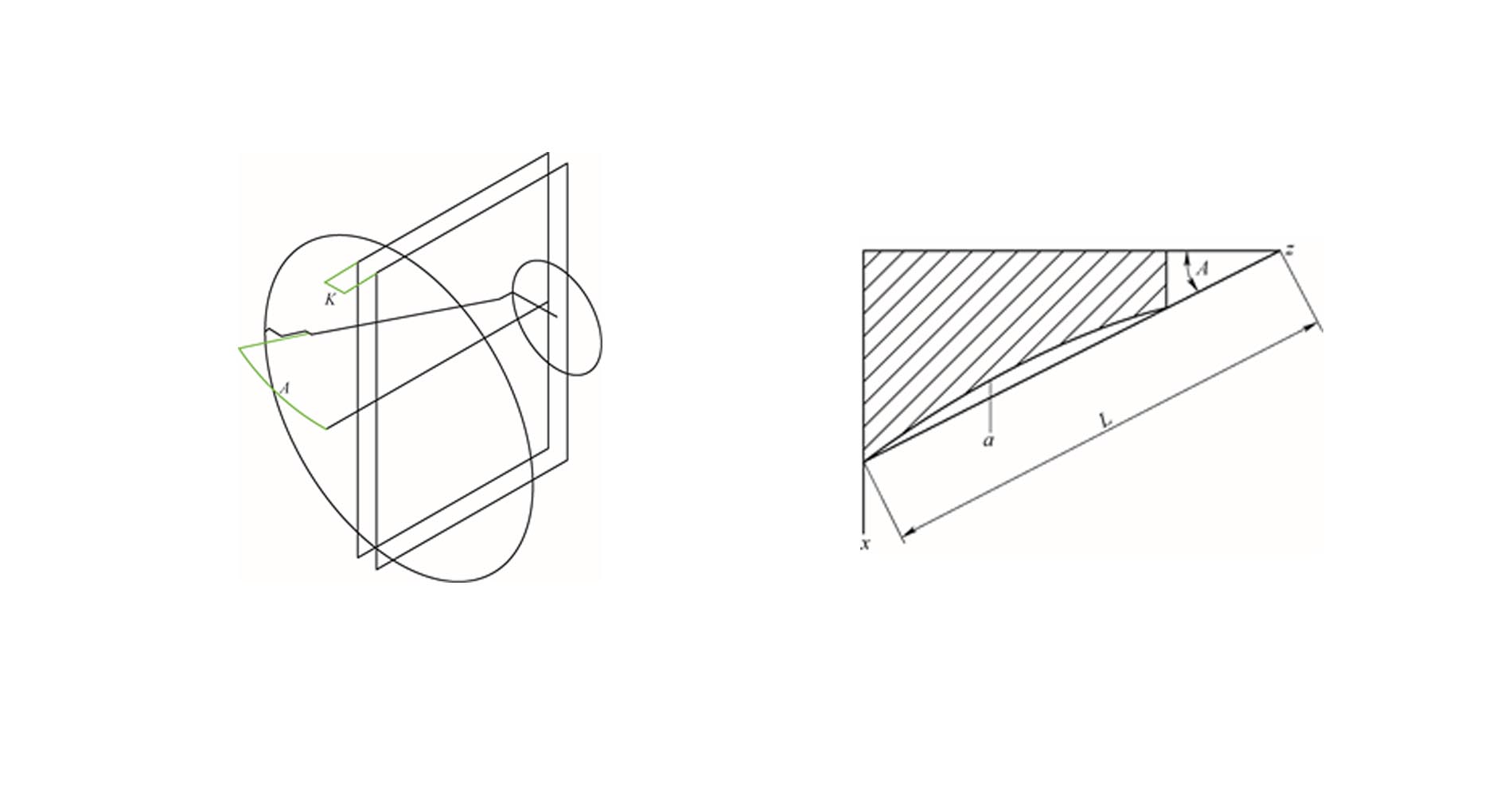
In product turning, the diameter difference between the large and small ends of the conical surface is 572mm, the Z-axis stroke is long, and the area of the conical surface is large. The hyperbolic error of the conical surface is very serious. The tool tip of the turning tool rotates off the center, so that the straight track of the tool tip does not coincide with the generatrix of the cone, and the inner and outer cones processed by the hyperbolic error are rotating hyperbolic surfaces. The straightness and taper angle requirements of the product are very high at 26.2°±2′, and the generation of hyperbolas must be controlled to the greatest extent. Two parallel surfaces cut a conical surface and intersect to form a hyperbolic intersection line. The formula is:
1=(y2/k2)+(x2/k2)+(tana2/k2) (1)
y is the Z-axis (length) direction value (mm), x is the X-axis (diameter) direction value (mm); a is the product taper (°); k is the distance between the two surfaces (the distance between the tool tip and the center of rotation , mm).
The maximum hyperbolic error generated by the vertical distance between parallel curved surfaces (one of which passes through the center of gyration) is the straightness error of the inner cone surface of the product, and the product technical requirement is less than 0.03mm.
By calculating the Z-axis stroke and the area of the conical surface when machining the inner and outer conical surfaces, it is concluded that the tip of the turning tool must be at the same height as the center of rotation of the cone, and the linear trajectory of the tool tip must coincide with the generatrix of the cone. The error of the center cannot be >0.08mm. The wall thickness of the finished car cone is 2.96-3.05mm, which meets the tolerance requirements, and the thickness difference between the upper and lower positions of the product cone wall is less than 0.05mm. Using three-coordinate measurement, the inner and outer circles are φ(329±0.05) mm, the roundness is less than 0.08mm, and the straightness of the cone surface is less than 0.03mm. Curve errors are effectively controlled.
Summarize
By calculating the Z-axis stroke and the area of the conical surface when machining the inner and outer conical surfaces, it is concluded that the tip of the turning tool must be at the same height as the center of rotation of the cone, and the linear trajectory of the tool tip must coincide with the generatrix of the cone. The error of the center cannot be >0.08mm. The wall thickness of the finished car cone is 2.96-3.05mm, which meets the tolerance requirements, and the thickness difference between the upper and lower positions of the product cone wall is less than 0.05mm. Using three-coordinate measurement, the inner and outer circles are φ(329±0.05) mm, the roundness is less than 0.08mm, and the straightness of the cone surface is less than 0.03mm. Curve errors are effectively controlled.