
Analysis of CNC mill a reverse countersink process. Multiple studies and field tests were conducted from different tools and processing methods. Identify improvement options through comparison. A homemade eccentric reverse scraper is used for specific processing steps and procedures. This change, after production verification and data analysis, solved the problem of anti-sink holes in deep cavities.
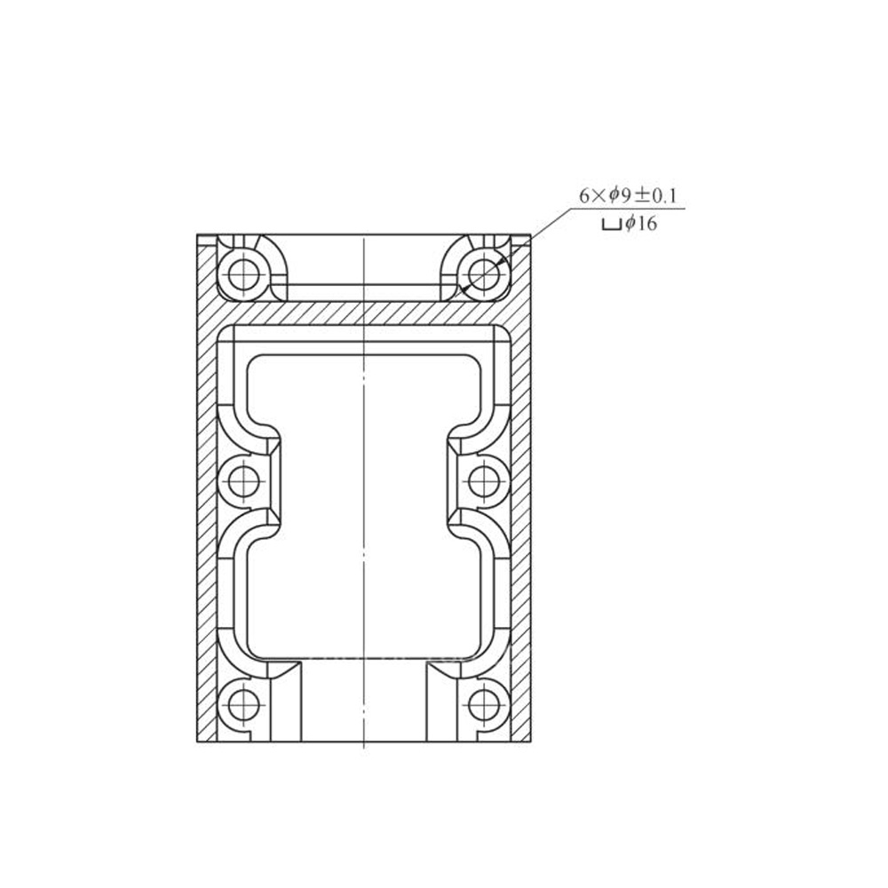
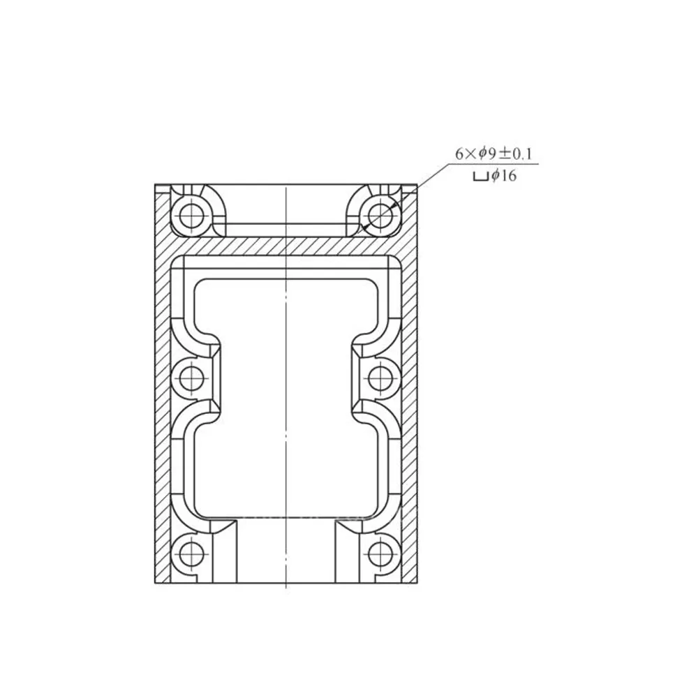
A certain part is the core load-bearing structural component of the high-speed rail device. It needs to withstand the test of multiple loads during high-speed rail operation. Its structural strength directly affects the operation of the high-speed rail. There are multiple reverse countersinks inside the deep cavity of this part. Ordinary tools are not accessible on machine tools. It is necessary to add a separate EDM process to mill a reverse countersink. The minimum processing time for each product is 2.5 hours. The processing efficiency is low and the surface quality is poor. Poor, and difficult to clamp and position.
To solve the problem of back counterboring processing, change the current situation of electric discharge machining, reduce processing costs, and improve processing efficiency, through investigating various back counterboring processing solutions, CNC milling of back counterboring was realized.
At present, the main types of reverse counterscraper tools include screw-locked counter-scrapers, mounted drive block-type counter-scrapers and eccentric counter-scrapers.
Comparison of various tool machining solutions- Mill a Reverse Countersink
Screw-locking anti-scraper processing steps: ① Extend the Z-axis of the tool holder. ②Lock the cutterhead with screws. ③ Turn forward for upward processing. ④Return the loosening screw and remove the cutterhead. ⑤The tool holder exits to complete processing. The advantages are tight installation, sufficient rigidity, replaceable blades, and low cost. The disadvantage is that it takes a lot of time to change the tool. There are currently many ways to improve this processing solution, such as changing the screw locking to a sleeve-type inlay. The rotating cutterhead will be stuck with the main tool bar during forward processing. There is no need to fix it with screws, which saves time. However, due to the front and rear middle frames After clamping and positioning, there are 4 countersunk holes in the cavity, and the rotating cutterhead cannot be disassembled and assembled. Therefore, the screw-locked counter-scraper processing method is not feasible.
Install the driving knife block anti-scraper. There are many ways to drive the tool block, such as opening the tool block by air or cutting fluid pressure, opening the tool block by a torque rod, opening the tool block by short taper or collision, and opening the tool block by inertia. The countersink hole on the back of the mid-frame product is a φ9mm slender hole, and a BIG standard multi-function counter scraper is used. It has a detachable, fan-blade blade holder structure. The blade holder can be automatically closed, and can be realized through simple forward and reverse programming of the spindle. When the insert holder is closed, it passes through the bottom hole, and when the insert holder is unfolded, cutting begins. Automated processing can be realized on vertical and horizontal machining centers. Processing steps: Invert the spindle and insert it into the bottom hole (the blade holder is open under the action of centrifugal force); when the blade holder contacts the bottom hole, it will automatically fold into the tool holder; continue feeding until the blade holder passes through the bottom hole. ; Make the spindle rotate forward and pull it up through cutting feed (start processing); when the back countersinking is completed, make the spindle back slightly and reverse it; while reversing, lift the spindle, and the insert holder can be folded into the tool holder from the bottom hole to pull out. Through many tests, the multi-functional anti-scraper is extremely efficient in processing normal back countersinking. However, because the back countersinking of the front and rear middle frame product parts is tangent to the side wall, when starting cutting, the insert seat does not have the side surface of the cutting edge. It will come into contact with the workpiece and damage the tool holder instantly, so this processing solution does not have stable production conditions.
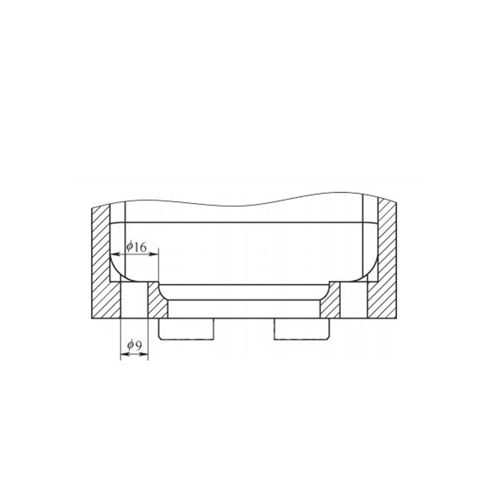
Eccentric anti-scraper. When choosing an eccentric counter-scraper, you must first consider that when the counter-scraper is installed on the spindle, the tip of the counter-scraper has directionality in the circumference. When changing the tool, the spindle needs to be positioned circumferentially. Therefore, when the tool change is completed, the tip of the counter-scraper on the spindle is at The circumference is directional. The spindle moves quickly without rotating. The center of the hole deviates from the center of the hole along the X-axis in the opposite direction of the tool tip. The deviation amount is >3.5mm [(large hole diameter 16mm – small hole diameter 9mm)/2] to ensure that the anti-scraper passes through the hole. will not interfere with the hole wall. When the reverse scraper countersinks the inner cylindrical hole at the bottom of the hole, the spindle does not move axially (pauses) and scrapes the bottom surface. The number of scraped circles is related to the spindle speed and pause time, and can be determined by the following formula: Number of circles = Spindle speed × pause time must ensure that the number of circles is an integer. Figure 7 shows the homemade anti-scraper that was trial-produced in the early stage. It is a self-made anti-scraper. Processing steps: ① Spindle positioning. ②Eccentric displacement (E value). ③Z axis goes deep. ④Recovery center (E value). ⑤ Turn forward for upward processing. ⑥Spindle positioning. ⑦Eccentric displacement (E value). ⑧Disengage upward to complete processing. This processing method does not require forward and reverse rotation, which can reduce the probability of damage; it reduces the tedious process of manually installing the rotating cutterhead, and the hole is formed in one go; it accepts customization in a variety of specifications, and if the countersink hole is much larger than the bottom hole, you can choose to import it Alloy steel, or plugged with carbide, or use a solid tungsten-based alloy as the body. However, the machine tool is required to have a directional stop function, otherwise it cannot be used.
Improved processing plan. For countersinking a φ16mm large hole, first design an eccentric anti-scraper with replaceable blades. The equipment selects a CNC machine tool with a spindle directional stop function, and moves 3.6mm in the opposite direction of the installed blade, so that the boring tool can pass through the φ9mm small hole smoothly. The anti-scraper moves a certain distance in the direction of the boring tool head to the X=0, Y=0 point (center of the hole), countersinks, pauses, that is, no feed cutting, to reduce the surface roughness value of the countersink; retreats, circular positioning , let the tool exit; the tool exits to complete processing.
The processing procedure is as follows:
N1 G90G54G00X3.6Y0.0; the anti-scraper moves quickly to deviate from the hole on the X-axis
Center 3.6mm
N2 G43Z180.0H06
N3 Z115.0
N4 X0.0S280M03; the anti-scraper returns to the center of the hole
N5 C0lZ125.0F36
N6 G04P450; pause for 0.45s, scrape the bottom surface
N7 G00 Z115.0 M05
N8 M19; spindle circumferential positioning
N9 X3.6
N10 G91 G28 Z0
N11 G49 G28 XO YO
After on-site production verification and finished product quality inspection, the improved processing plan is economical and practical. It uses an eccentric counter-scraper with replaceable blades and solves the problem of back countersinking inside the deep cavity through processing procedures on CNC machine tools, laying the foundation for future deep hole lathes. Milling process design provides ideas for tool expansion.