CNC parts inspection is a key step to ensure the quality of CNC machined parts.
Xi’an Hi-Precision Machinery Co., Ltd is ISO 9001:2015 certified, we adhere to strict guidelines and conduct quality inspection of CNC parts to provide our customers with quality parts.
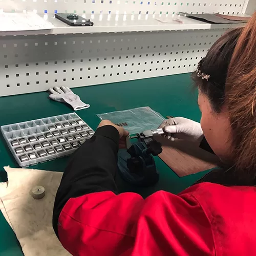
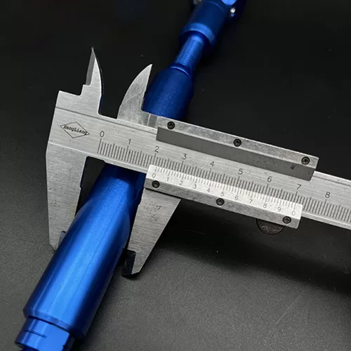
The CNC machining parts quality inspection service we provide you includes two inspection services: surface finish inspection and tolerance inspection.
If you need CNC machining services, please contact us.
Xi’an Hi-Precision Machinery Co., Ltd is a Chinese CNC machining shop. We manufacture various precision non-standard parts for various industries around the world. Our manufacturing is based on solid quality control and is backed by the ISO 9001:2015 quality system. Every new parts order goes into our quality inspection process and is ultimately delivered to our customers with a 100% pass rate. Our team utilizes a variety of quality inspection equipment to ensure your machined parts and assemblies meet or exceed your requirements.
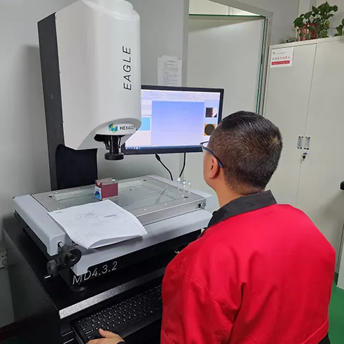
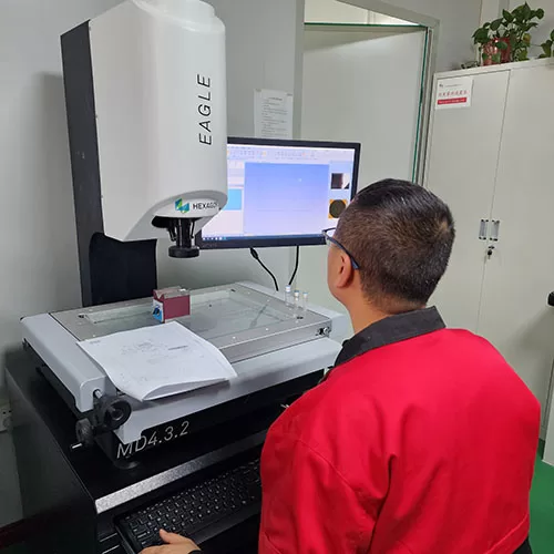
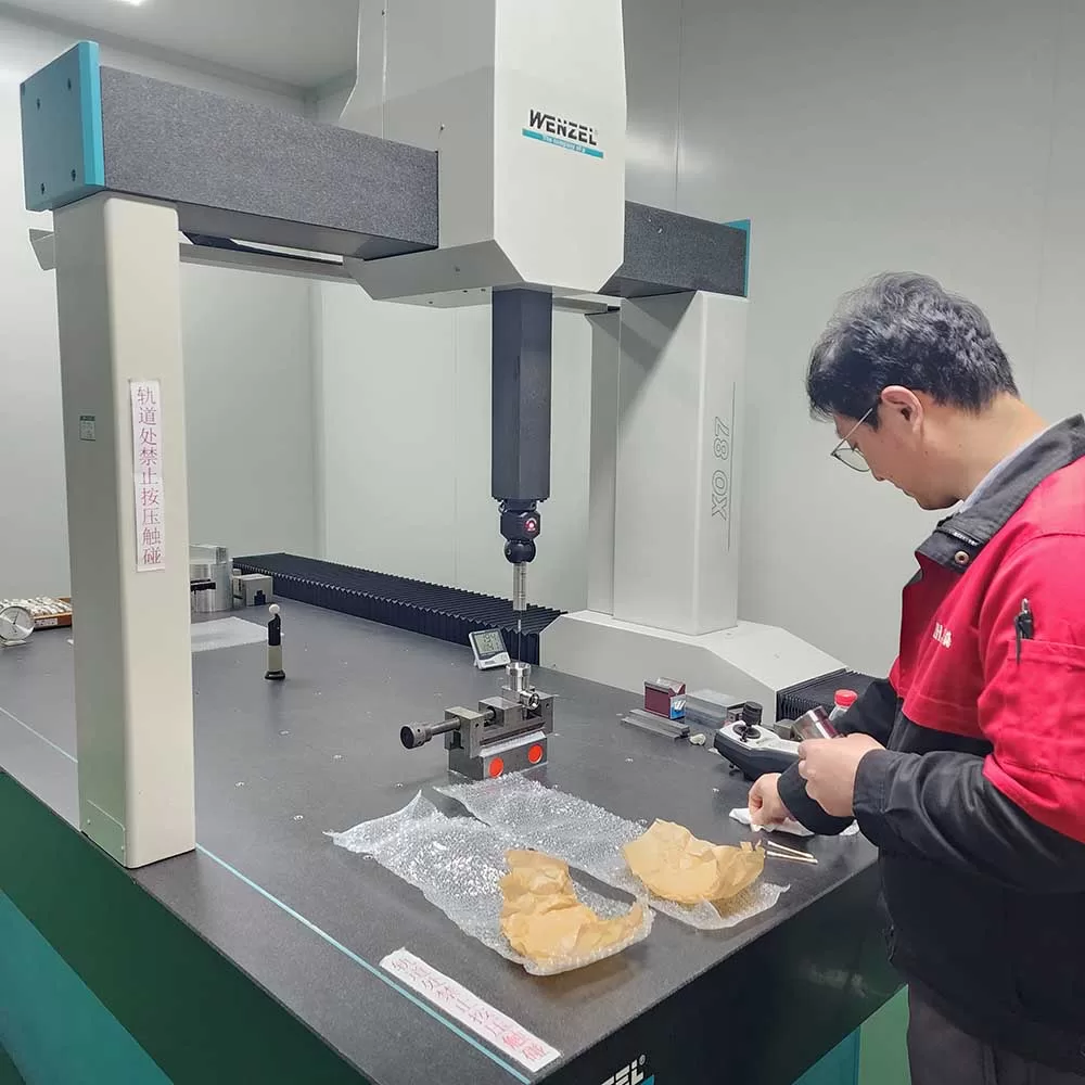
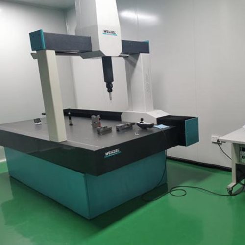
We use state-of-the-art fully automatic CMM, Sunnen gauges, optical comparators, profilometers, hardness testers, micrometers and other equipment to measure and verify the external and internal dimensions, geometry, etc. of parts. Our company has various measuring tools for machining process verification. All of our facilities are climate controlled at 70°F ±2° with a relative humidity of less than 40% to ensure a stable testing and manufacturing environment.
The CMM probe moves in the Z, Y, and When observing changes during processing, processing parameters can be quickly adjusted. The CMM test process can successfully measure and verify even the most complex part geometries.
View the CNC machined parts we made.
Our CNC parts inspection mainly includes: Heat treatment: heat treatment, induction hardening | Coating: chromium plating, electroplating, anodizing, phosphating, painting | EDM (Electrical Discharge Machining): wire cutting, sinker | Deep hole machining: gun drilling, honing | Gear cutting and grinding: spiral Gears, Splines | Surface Treatment: Super Finishing, Micromachining, Microfinishing | Machined Part Balancing | Porosity Impregnation: Castings, Powder Metals, Weldments | Welding: Conventional, Friction.